Articles by "Mechanical Engineering"

3D printing Aerodynamic engineering Aeronautical engineering Aeronautical engineering books Airports Architecture Artificial intelligence Automobiles Blast Resistant Design Books Bridges Building Codes Cabin Systems Civil Engineering Codes Concrete Conferences Construction Management Construction Materials Cooling Cryptocurrency Dams Do it Yourself Docks and Harbours Downloads Earthquake Engineering Electronics Engineering Engines Environmental Design & Construction Environmental Engineering Estimation Fluid Mechanics Fluid Mechanics Books Formwork design foundation engineering General Geotech Books Geotechnical Engineering Global Positioning System HVAC Hydraulics Hydraulics Books Hydro Power Hydrology Irrigation Engineering Machinery Magazines Management Books Masonry Mechanical Engineering Mechanics Mechanics Books Miscellaneous Books Modern Steel Construction Nanotechnology Natural Hazards Network Security Engineer Networking Systems News Noise and Attenuation Nuclear Engineering Nuclear Hazards to Buildings Pavement Design Prestressed Concrete Project Management Project Management Books Quantity Survey Quantity Survey Books railways RCC Structural Designing Remote Sensing Remote Sensing and GIS Books Renewable Energy Reports Resume Roads scholarships Smart devices Software Software Engineering Soil Mechanics Solar Energy Special Concrete Spreadsheets Steel Steel Spreadsheets Structural Analyses structures Structures Books Surveying Surveying Books Testing Thermodynamics Thesis Transportation Books Transportation Engineering Tunnel Engineering Wind Energy Zero Energy Buildings
Showing posts with label Mechanical Engineering. Show all posts

Force

The concept of force can be taken from our daily experience. Although forces cannot be seen or directly observed, we are familiar with their effects. For example, a helical spring stretches when a weight is hung on it or it is pulled. Our muscle tension conveys a qualitative feeling of the force in the spring. Similarly, a stone is accelerated by gravitational force during free fall, or by muscle force when it is thrown. Also, we feel the pressure of a body on our hand when we lift it. Assuming that gravity and its effects are known to us from experience, we can characterize a force as a quantity that is comparable to gravity.

In statics, bodies at rest are investigated. From experience we know that a body subject solely to the effect of gravity falls. To prevent a stone from falling, to keep it in equilibrium, we need to exert a force on it, for example our muscle force. In other words:
A force is a physical quantity that can be brought into equilibrium with gravity.
Characteristics and Representation of a Force
What is a Force and How to Represent it?
Figure 1
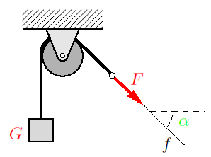
A single force is characterized by three properties: magnitude, direction, and point of application. The quantitative effect of a force is given by its magnitude. A qualitative feeling for the magnitude is conveyed by different muscle tensions when we lift different bodies or when we press against a wall with varying intensities. The magnitude F of a force can be measured by comparing it with gravity, i.e., with calibrated or standardized weights. If the body of weight G in Fig. 1 is in equilibrium, then F = G. The “Newton”, abbreviated N, is used as the unit of force.

From experience we also know that force has a direction. While gravity always has an effect downwards (towards the earth’s center), we can press against a tabletop in a perpendicular or in an inclined manner. The box on the smooth surface in Fig. 2 will move in different directions, depending on the direction of the force exerted upon it. The direction of the force can be described by its line of action and its sense of direction (orientation). In Fig. 1, the line of action f of the force F is inclined under the angle α to the horizontal. The sense of direction is indicated by the arrow.

What is a Force and How to Represent it?
Figure 2
What is a Force and How to Represent it?
Figure 3
Finally, a single force acts at a certain point of application. Depending on the location of point A in Fig. 2, the force will cause different movements of the box. A quantity determined by magnitude and direction is called a vector. In contrast to a free vector, which can be moved arbitrarily in space provided it maintains its direction, a force is tied to its line of action and has a point of application.
Therefore, we conclude:
The force is a bound vector.

According to standard vector notation, a force is denoted by a boldfaced letter, for example by F, and its magnitude by |F| or simply by F. In figures, a force is represented by an arrow, as shown in Figs. 1 and 2. Since the vector character usually is uniquely determined through the arrow, it is usually sufficient to write only the magnitude F of the force next to the arrow. In Cartesian coordinates (see Fig. 3), the force vector can be represented using the unit vectors ex, ey, eby,

What is a Force and How to Represent it?

Applying Pythagorean theorem in space, the force vector’s magnitude F is given by

What is a Force and How to Represent it?

The direction angles and therefore the direction of the force follow from
What is a Force and How to Represent it?

The theoretical basis of the method of joints for truss analysis has already been discussed in this article '3 methods for truss analysis'. " 2 examples will be presented in this this article to clarify those concepts further.

Example 1

The truss shown in Fig. 1 is loaded by an external force F. Determine the forces at the supports and in the members of the truss.

Solved Examples for Method of Joints for Truss Analysis
Figure. 1
Solution:

Fig. 1a represents a simple truss that is completely constrained against motion. Therefore, it is statically determinate. The members of the truss are numbered in the free-body diagram of the complete truss (Fig. 1b). Zero-force members are identified by inspection and marked with zeroes: member 4 (according to Rule 2), the members 5 and 9 (Rule 3) and the members 10 and 13 (Rule 1). To further reduce the number of unknown forces, we compute the support forces by applying the equilibrium conditions to the whole truss.
Solved Examples for Method of Joints for Truss Analysis
Fig. 1c shows the free-body diagrams of the joints. As previously stated, we assume that every member is subjected to tension. Accordingly, all of the corresponding arrows point away from the joints. Zero-force members are omitted in the free-body diagrams. Therefore, joint VII need not be considered. Applying the equilibrium conditions to each joint yields
Solved Examples for Method of Joints for Truss Analysis
These are 11 equations for the 8 unknown forces in the members and the 3 forces at the supports. Since the support forces have been computed in advance and are already known, the analysis is simplified, and three equations may be used as a check on the correctness of the results. Using the geometrical relations
Solved Examples for Method of Joints for Truss Analysis
It is useful to present the results in dimensionless form in a table, including negative signs:
Solved Examples for Method of Joints for Truss Analysis
The negative values for the members 1, 2, 6, 7 and 11 indicate that these members are under compression.

Example 2

Fig. 2 shows a spatial truss loaded by two external forces F at the joints IV and V. Compute the forces in the members 1-6.
Solved Examples for Method of Joints for Truss Analysis
Figure. 2
Solution:

We free the joints V and IV by passing imaginary cuts through the bars, and we assume that the members 1-6 are in tension. The vector equations of equilibrium for these joints are given by
Solved Examples for Method of Joints for Truss Analysis

The initially unknown unit vectors can be determined from the vectors connecting adjacent joints, e.g., for e(V/VI) we obtain
Solved Examples for Method of Joints for Truss Analysis
Similarly, the other unit vectors are

Solved Examples for Method of Joints for Truss Analysis

Introducing these into the two vector equations we get the six scalar equations

Solved Examples for Method of Joints for Truss Analysis
Their solution yields the forces

Solved Examples for Method of Joints for Truss Analysis

A truss is a structure composed of slender members that are connected at their ends by joints. The truss is  one of the most important structures in engineering applications. After studying this chapter, students should be able to recognise if a given truss is statically and kinematically determinate. In addition, they will become familiar with methods to determine the internal forces in a statically determinate truss.

A structure that is composed of straight slender members is called a truss. To be able to determine the internal forces in the individual members, the following assumptions are made:

1. The members are connected through smooth pins (frictionless joints).
2. External forces are applied at the pins only.

A truss that satisfies these assumptions is called an “ideal truss”. Its members are subjected to tension or to compression only. In real trusses, these ideal conditions are not exactly satisfied. For example, the joints may not be frictionless, or the ends of the members may be welded to a gusset plate. Even then, the assumption of frictionless pin-jointed connections yields satisfactory results if the axes of the members are concurrent at the joints. Also, external forces may be applied along the axes of the members (e.g., the weights of the members). Such forces are either neglected (e.g., if the weights of the members are small in comparison with the loads) or their resultants are replaced by statically equivalent forces at the adjacent pins.
Statically Determinate Trusses
Fig. 1

In this article we focus on plane trusses; space trusses can be treated using the same methods. As an example, consider the truss shown in Fig. 1. It consists of 11 members which are connected with 7 pins (the pins at the supports are also counted). The members are marked with Arabic numerals and the pins with Roman numerals.

To determine the internal forces in the members we may draw a free-body diagram for every joint of the truss. Since the forces at the pins are concurrent forces, there are two equilibrium conditions at each joint. In the present example, we thus have 7·2 = 14 equations for the 14 unknown forces (11 forces in the members and 3 forces at the supports).

A truss is called statically determinate if all the unknown forces, i.e., the forces in the members and the forces at the supports, can be determined from the equilibrium conditions. Let a plane truss be composed of m members connected through j joints, and let the number of support reactions be r. In order to be able to determine the m + r unknown forces from the 2j equilibrium conditions, the number of unknowns has to be equal to the number of equations:

2 j = m + r (Equation 1)

This is a necessary condition for the determinacy of a plane truss. As we shall discuss later, however, it will not be sufficient in cases of improper support or arrangement of the members. If the truss is rigid, the number of support reactions must be r = 3. In the case of a space truss, there exist three conditions of equilibrium at each joint, resulting in a total of 3 j equations.
Therefore,
3 j = m + r (Equation 2)


is the corresponding necessary condition for a space truss. If the truss is a rigid body, the support must be statically determinate: r = 6.
Understanding trusses
Fig. 2

For the truss shown in Fig. 2a we have j = 7, m = 10 and r = 2 · 2 (two pin connections). Hence, since 2 · 7 = 10+4, the necessary condition (Equation 1) is satisfied. The truss is, in addition, completely constrained against motion. Therefore, it is statically determinate.

A truss that is completely constrained against motion is called a kinematically determinate truss. In contrast, a truss that is not a rigid structure and therefore able to move is called kinematically indeterminate. This is the case if there are fewer unknowns than independent equilibrium conditions. If there are more unknowns than equilibrium conditions, the system is called statically indeterminate. We shall only consider trusses that satisfy the necessary conditions stated in Equations (1) or (2), respectively. Even then, a truss will not be statically determinate if the members or the supports are improperly arranged. Consider, for example, the trusses shown in Figs. 2b and 2c. With j = 6, m = 9 and r = 3 the necessary condition (1) is satisfied. However, the members 7 and 8 of the truss in Fig. 2b may rotate about a finite angle ϕ, whereas the members 5 and 8 of the truss in Fig. 2c may rotate about an infinitesimally small angle dϕ. Each of the improperly constrained trusses is statically indeterminate.

These articles might also interest you:
 Analysis of 2D Truss Structure in SAP 2000
3 Methods for Truss Analysis

With an incomprehensible quantity of concrete used in it, the world's largest dam proudly stands on China's Yangtze River. It is a hydroelectric dam situated in Yiling District, Yichang, Hubei province, China. The dam has increased the shipping capacity of Yangtze river in addition to power generation. Some facts are as follows,
Name: Three Gorges Dam, China (长江三峡水利枢纽工程)
Completion of dam body: 2006
Total capacity 39.3 km3
Time to build: 17 years
Cost to build: $22 billion
No. of main turbines: 32
Total power generation capacity: 22,500 MW

World's Largest Dam: Three Gorges Dam, China (长江三峡水利枢纽工程)
Image: PopularMechanics

Like, share and comment if you find this article interesting.

When a beam is subjected to applied forces, internal forces develop in the beam. Since the beam has supports and the system is in an equilibrium condition, the beam should resist these internal forces. This type of force is called shear force, or simply shear. The magnitude of the shear has a direct effect on the magnitude of the shear stress in the beam, and also on the design and analysis of the structural members.
Shear forces develop along the entire length of the beam, and their magnitude varies at each cross section of the beam. They actually act perpendicularly to the longitudinal axis of the beam. Our main objectives in finding the shear in beams are twofold. First, we have to know the maximum value of the shear in order to design the beam properly so that it can resist overall shear and will not fail when it is loaded.
The second objective is to calculate the values of shear along the length of the beam, so that we can find out where the beam fails under bending and where the shear value is zero.

As mentioned earlier, the designer must first know the magnitude of the shear force at any section of the beam to get the right picture of beam design. The magnitude of shear force at any section of the beam is equal to the sum of all the vertical forces either to the right or to the left of the section. To compute the shear force for any section of the beam, we simply call the upward forces (reactions) positive and downward forces (loads) negative. Then, the magnitude of the shear force at any section of the beam is equal to sum of the reactions minus the sum of the loads to the left of the section. This can be stated as:
Shear = Reactions - Loads
Example:
Find the shear force at sections C, D, and E for the simply supported beam shown (Fig. 1).
Computation of Shear Force
Figure 1
First, we calculate the reactions.

RA + RB = 15,000 lb 

Using the moment equilibrium equation,

RA(10) - 5000(8) -10,000(2) = 0
10(RA) = 60,000
RA = 6000 lb
and
RB = 9000 lb

Point C

We usually represent a shear force by V, and we designate this shear force at C as Vc.
Vc = +6000 - 0 = 6000lb

Point D

Vd =  +6000 - 5000 = +1000 lb

Point E


Ve = +6000 - 5000 - 10,000 = -9000 lb

Stepan Prokopovych Timoshenko was born on December 22, 1878 in the village of Shpotivka in the Ukrain. Timoshenko’s early life seems to have been a happy one in pleasant rural surroundings. He studied at a “realnaya” school from 1889 to 1896.
Stephen P. Timoshenko (1878–1972)

Timoshenko continued his education towards a university degree at the St. Petersburg Institute of Engineering. After graduating in 1901, he stayed on teaching in this same institution from 1901 to 1903 and then worked at the St. Petersburg Polytechnic Institute under Viktor Kyrpychov 1903–1906. His restlessness and discontent with the educational system extant in Russia at that time motivated the young Timoshenko to venture out to explore, examine, and assimilate diverse pedagogical views and cultures in France, Germany, and England. In 1905 he was sent for 1 year to the University of Göttingen where he worked under Ludwig Prandtl.

In the fall of 1906 he was appointed to the Chair of Strengths of Materials at the Kyiv Polytechnic Institute. Thanks to his tormented spirit at this institute, Timoshenko took the plunge to writing his maiden Russian classic, Strength of Materials in 1908 (Part I) and 1910 (Part II). From 1907 to 1911 as a professor at the Polytechnic Institute he did research in the area of finite element methods of elastic calculations, and did excellent research work on buckling. He was elected dean of the Division of Structural Engineering in 1909.

In 1911 he was awarded the D. I. Zhuravski prize of St. Petersburg; he went there to work as a Professor in the Electro-technical Institute and the St. Petersburg Institute of the Railways (1911–1917). During that time he developed the theory of elasticity and the theory of beam deflection, and continued to study buckling. In 1922 Timoshenko moved to the United States where he worked for the Westinghouse Electric Corporation from 1923 to 1927, after which he became a faculty professor at the University of Michigan where he created the first bachelor’s and doctoral programs in engineering mechanics. His textbooks have been published in 36 languages. His first textbooks and papers were written in Russian; later in his life, he published mostly in English.

It is a well-known fact that diamond is the hardest material on the planet. However, diamond lost its status of the hardest substance when scientists at the North Carolina State University discovered a new, harder-than-diamond form of carbon.

The research team found a new phase of carbon, called the Q-carbon.

'Q' Carbon Surpassed Diamond as the Hardest Material on the Planet - Extreme Discovery


(Image modified from: Jagdish Narayana & Anagh Bhaumik)

The new phase of carbon is quite different from graphite and diamond. Q-Carbon shows some unique and quite unexpected properties like ferromagnetic nature. Another unusual feature of this phase of carbon is that it begins to glow in the presence of energy. See more images from various experiments below:


Q carbon engineersdaily.com

(Image Source: Jagdish Narayana & Anagh Bhaumik)

Q carbon engineersdaily.com

(Image Source: Jagdish Narayana & Anagh Bhaumik)

Q carbon engineersdaily.com

(Image Source: Jagdish Narayana & Anagh Bhaumik)

Q carbon engineersdaily.com
(Image Source: Jagdish Narayana & Anagh Bhaumik)

Q carbon engineersdaily.com

(Image Source: Jagdish Narayana & Anagh Bhaumik)

Q carbon engineersdaily.com

(Image Source: Jagdish Narayana & Anagh Bhaumik)

The research has been published in the Journal of Applied Physics. The Q-phase of carbon was created by focusing a laser beam on amorphous carbon for 200-nanoseconds. The temperature of the amorphous carbon sample rose quickly and was cooled down by the process of quenching to create Q-Carbon.

This recent discovery will be a massive breakthrough in the domain of structures and materials. The new hardest material on the planet might be used for the fabrication of prosthetic structures, improvement of the equipment used for deep drilling, as well as developing new, brighter screens for the smartphones and televisions.

June, 2016
Rolls-Royce just unveiled a concept car, and it is one of the most spectacular, yet vastly unusual, concept automobiles that has ever been seen. The unveil took place as a 360˚ Youtube video that takes you through a virtual reality experience with the help of the virtual assistant named “Eleanor.” The car resembles something straight out of Tron, and it is fully autonomous. Enter the 103EX, an ambitious design that Rolls-Royce wants you to make your grand entrance in. Check out the immersive video below, and don’t forget that you can control the perspective in this 360˚ experience.


When you first get a glimpse of the car, you have to stop and wonder if Rolls-Royce is serious, because of just how different it looks. The goal of the new concept isn’t to display one singular car, rather a vision of inspiring the driver to break down the boundaries of what they think a luxury car is, according to the Verge.
“Looking towards the next 100 years, each and every Rolls-Royce will be a unique work of art. Shape, size and silhouette – you will be able to craft your vision entirely from the wheels up.” ~ Rolls-Royce
For another look at the car, watch the below video guided again by that mysterious AI voice, Eleanor.

These fully autonomous luxurious cars are what Rolls-Royce believes the visionaries of the future will be riding in. You have to admit, the 103EX concept does look like something straight out of a science fiction movie. The car looks massive, and it is. Stretching over 20 feet for a car that only holds 2 people on a fancy couch, whoever rides inside will make quite the entrance wherever they arrive, according to the Quartz. All-electric is the vision of the future of Rolls-Royce vehicles, along with a luggage storage compartment and interior design rivaling many foreign palaces.

Rolls-Royce Unveils 103EX Concept in Stunning 360˚ VR
[Image Source: Rolls-Royce]

All of this futuristic technology is part of Rolls-Royce’s parent company BMW’s centennial celebration. The company also unveiled a transparent Mini Cooper concept which is equally as stunning as the Rolls-Royce 103EX. The future of luxury is going to look, well, futuristic.

Many European countries have been making the shift to electric vehicles and Germany has just stated that they plan to ban the sale of gasoline and diesel powered vehicles by 2030. The country is also planning to reduce its carbon footprint by 80-95% by 2050, sparking a shift to green energy in the country. Effectively, the ban will encompass the registration of new cars in the country as they will not allow any gasoline powered vehicle to be registered after 2030, according to The Globe and Mail.

Part of the reason this ban is being discussed and implemented is because energy officials see that they will not reach their emissions goals by 2050 if they do not eliminate a large portion of vehicle emissions. The country is still hopeful that it will meet its emissions goals, like reducing emissions by 40% by 2020, but the acceptance of electric cars in the country has not occurred as fast as expected.

Other efforts to increase the use of electric vehicles include plans to build over 1 million hybrid and electric battery plugins across the country. By 2030, Germany plans on having over 6 million plugins installed. According to the International Business Times, electric car sales are expected to increase as Volkswagen is still recovering from its emissions scandal.

Germany Banning all Vehicle Emissions by 2030
A test device checks exhaust emissions of a VW Golf 2.0 TDI car in Frankfurt/Oder, Germany. Photograph courtesy: Patrick Pleul/EPA

Currently, there are only around 155,000 registered hybrid and electric vehicles on German roads, dwarfed by the 45 million gasoline and diesel cars currently driving there too. As countries continue setting goals of reducing emissions, greater steps are going to need to be taken to have a noticeable effect on the surrounding environment. While the efforts are certainly not futile, the results of such bans will likely only start to be seen by generations down the line, bettering the world for the future.

While the elongation or contraction of axially loaded members along their longitudinal axes is usually of little consequence, beams may experience excessive deflection perpendicular to their longitudinal axes, making them unserviceable. Limits on deflection are based on several considerations, including minimizing vibrations, thereby improving occupant comfort; preventing cracking of ceiling materials, partitions, or cladding supported by the beams; and promoting positive drainage (for roof beams) in order to avoid ponding of water at midspan. These limits are generally expressed as a fraction of the span, L (Table 1).

Overview: Deflection in Beams

Formulas for the calculation of maximum deflection are shown in Table 2, along with additional values for the recommended minimum depth of reinforced concrete spanning elements.

Overview: Deflection in Beams

The maximum (mid span) deflection, Δ, of a uniformly loaded simple span can also be found from the equation:
where w distributed load (lb/in. or kips/in.), L span (in.), E modulus of elasticity (psi or ksi), and I moment of inertia (in 4 ). When using Equation 8.1 with L in feet, w in lb/ft or kips/ft, E in psi or ksi (compatible with load, w ), and I in in4, as is most commonly done, multiply the expression by 123 to make the units consistent.
 

If a member is loaded beyond its ultimate stress, it will fail or rupture. In engineering structures, it is essential that the structure not fail. Thus, the design is based on some lower value called allowable stress or design stress. If, for example, a certain type of steel is known to have an ultimate strength of 110,000 psi, a lower allowable stress would be used for design, say 55,000 psi. This allowable stress would allow only half the load the ultimate stress would allow. Allowable stress values are different for different materials, and they are tabulated and recommended by the International Building Code Association.
The ratio of the ultimate stress to the allowable stress is known as the factor of safety.

factor of safety = ultimate strength / allowable stress
Allowable Stress
Image courtesy: http://www.smpes.com
Example
Determine the required size for a steel rod to support a tensile load of 50,000 lb if the allowable tensile stress of the steel is 25, 000 psi.

Solution
σ = F/A
or
A = F/σ = 50, 000lb/25, 000psi = 2in2
A = πD2/4 = 2in2
Solving for D, we have:
D = 1.6 in

Features of WaterCAD

Design and modeling of water distribution have some long tedious empirical formulas like Hardy Cross Method and other such methods which solves the network diagrams of pipes and water distribution network.

WaterCAD has a name and have got quality in it that can help you design and model the water distribution system upto optimum level without any problem.

Graphical User Interface

WaterCAD helps engineers to design and analyze complex pressurized piping systems. WaterCAD has a unique feature of graphical interface that it can be used as stand-Alone or can be used along with traditional and leading CAD software i.e. AUTOCAD.

Modeling and Simulation
Bentley Water CAD V8i free download
This tedious and long term repetitive calculation can be avoided by using the computer as our helper. There are a lot of softwares available in the market that can do the water quality modeling solution for water distribution system for example EPA Net and Water CAD.

With the help of WaterCAD you can build network model and perform steady-state analysis, you can perform extended period simulation, precise results can be developed using reports, fire flow analysis, water quality analysis, energy costs, pressure dependent demands, criticality and segmentation.
WaterCAD has special Engineering Libraries in which Transient Valve Curve Editor and Pump Curve editor is a robust inbuilt tools.

WaterCAD has efficient Modeling capabilities that let you model and optimize a distribution system, perform steady-state / extended period simulation, global demand and roughness adjustements can be made, data can be checked and validated,

Download Bentley WaterCAD In this post I am going to share with you the free download link with which you can freely and easily download Bentley WaterCAD V8i for free.

Download Bentley WaterCAD V8i for free

Disclaimer: We don't upload any software neither sell them. All the files are uploaded on external servers. The software name and its logo are trademarks of the respective publisher.


Structural members are usually classified according to the types of loads that they support. For instance, an axially loaded bar supports forces having their vectors directed along the axis of the bar, and a bar in torsion supports torques (or couples) having their moment vectors directed along the axis.
Beams are structural members subjected to lateral loads, that is, forces or moments having their vectors perpendicular to the axis of the bar.
The beams shown in Fig. 1 are classified as planar structures because they lie in a single plane. If all loads act in that same plane, and if all deflections (shown by the dashed lines) occur in that plane, then we refer to that plane as the plane of bending.
Examples of beams subjected to lateral loads
FIG. 1 Examples of beams subjected to lateral loads
Beams are usually described by the manner in which they are supported. For instance, a beam with a pin support at one end and a roller support at the other (Fig. 2a) is called a simply supported beam or a simple beam. The essential feature of a pin support is that it prevents translation at the end of a beam but does not prevent rotation. Thus, end A of the beam of Fig.2a cannot move horizontally or vertically but the axis of the beam can rotate in the plane of the figure. Consequently, a pin support is capable of developing a force reaction with both horizontal and vertical components (HA and RA), but it cannot develop a moment reaction.
Types of beams: (a) simple beam, (b) cantilever beam, and (c) beam with an overhang
FIG. 2 Types of beams: (a) simple beam, (b) cantilever beam, and (c) beam with an overhang
At end B of the beam (Fig.2a) the roller support prevents translation in the vertical direction but not in the horizontal direction; hence this support can resist a vertical force (RB) but not a horizontal force. Of course, the axis of the beam is free to rotate at B just as it is at A. The vertical reactions at roller supports and pin supports may act either upward or downward, and the horizontal reaction at a pin support may act either to the left or to the right.
Types of connections
FIG.3 Beam supported on a wall: (a) actual construction, and
(b) representation as a roller support.
Beam-to-column connection:(c) actual
construction, and (d) representation as a pin support.

The beam shown in Fig.2b, which is fixed at one end and free at the other, is called a cantilever beam. At the fixed support (or clamped support) the beam can neither translate nor rotate, whereas at the free end it may do both. Consequently, both force and moment reactions may exist at the fixed support.

The third example in the figure is a beam with an overhang (Fig.2c). This beam is simply supported at points A and B (that is, it has a pin support at A and a roller support at B) but it also projects beyond the support at B. The overhanging segment BC is similar to a cantilever beam except that the beam axis may rotate at point B.

When drawing sketches of beams, we identify the supports by conventional symbols, such as those shown in Fig.2. These symbols indicate the manner in which the beam is restrained, and therefore they also indicate the nature of the reactive forces and moments. However, the symbols do not represent the actual physical construction. For instance, consider the examples shown in Fig.3. Part (a) of the figure shows a wide-flange beam supported on a concrete wall and held down by anchor bolts that pass through slotted holes in the lower flange of the beam. This connection restrains the beam against vertical movement (either upward or downward) but does not prevent horizontal movement.

Also, any restraint against rotation of the longitudinal axis of the beam is small and ordinarily may be disregarded. Consequently, this type of support is usually represented by a roller, as shown in part (b) of the figure.
Beam-to-column connection with one beam attached to column flange and other attached to column web
Beam-to-column connection with one beam attached to column flange and other attached to column web (Joe Gough/Shutterstock)


The second example (Fig.3c) is a beam-to-column connection in which the beam is attached to the column flange by bolted angles. (See photo.) This type of support is usually assumed to restrain the beam against horizontal and vertical movement but not against rotation (restraint against rotation is slight because both the angles and the column can bend). Thus, this connection is usually represented as a pin support for the beam (Fig.3d).

The last example (Fig.3e) is a metal pole welded to a base plate that is anchored to a concrete pier embedded deep in the ground. Since the base of the pole is fully restrained against both translation and rotation, it is represented as a fixed support (Fig.3f ).

The task of representing a real structure by an idealized model, as illustrated by the beams shown in Fig.2, is an important aspect of engineering work. The model should be simple enough to facilitate mathematical analysis and yet complex enough to represent the actual behavior of the structure with reasonable accuracy. Of course, every model is an approximation to nature. For instance, the actual supports of a beam are never perfectly rigid, and so there will always be a small amount of translation at a pin support and a small amount of rotation at a fixed support. Also, supports are never entirely free of friction, and so there will always be a small amount of restraint against translation at a roller support. In most circumstances, especially for statically determinate beams, these deviations from the idealized conditions have little effect on the action of the beam and can safely be disregarded.

Types of Loads

Several types of loads that act on beams are illustrated in Fig.2. When a load is applied over a very small area it may be idealized as a concentrated load, which is a single force. Examples are the loads P1, P2, P3, and P4 in the figure. When a load is spread along the axis of a beam, it is represented as a distributed load, such as the load q in part (a) of the figure. Distributed loads are measured by their intensity, which is expressed in units of force per unit distance (for example, newtons per meter or pounds per foot). A uniformly distributed load, or uniform load, has constant intensity q per unit distance (Fig.2a). A varying load has an intensity that changes with distance along the axis; for instance, the linearly varying load of Fig.2b has an intensity that varies linearly from q1 to q2. Another kind of load is a couple, illustrated by the couple of moment M1 acting on the overhanging beam (Fig.2c).

We assume in this discussion that the loads act in the plane of the figure, which means that all forces must have their vectors in the plane of the figure and all couples must have their moment vectors perpendicular to the plane of the figure. Furthermore, the beam itself must be symmetric about that plane, which means that every cross section of the beam must have a vertical axis of symmetry. Under these conditions, the beam will deflect only in the plane of bending (the plane of the figure).

Reactions

Finding the reactions is usually the first step in the analysis of a beam. Once the reactions are known, the shear forces and bending moments can be found, as described later in this chapter. If a beam is supported in a statically determinate manner, all reactions can be found from free-body diagrams and equations of equilibrium.
Internal releases and end supports in model of bridge beam
(Courtesy of the National Information Service for Earthquake
Engineering EERC, University of California, Berkeley.)


In some instances, it may be necessary to add internal releases into the beam or frame model to better represent actual conditions of construction that may have an important effect on overall structure behavior. For example, the interior span of the bridge girder shown in Fig.4 is supported on roller supports at either end, which in turn rest on reinforced concrete bents (or frames), but construction details have been inserted into the girder at either end to ensure that the axial force and moment at these two locations are zero. This detail also allows the bridge deck to expand or contract under temperature changes to avoid inducing large thermal stresses into the structure.
Types of internal member releases for two-dimensional beam and frame members
FIG.4 Types of internal member releases for two-dimensional beam and frame members
To represent these releases in the beam model, a hinge (or internal moment release, shown as a solid circle at each end) and an axial force release (shown as a C-shaped bracket) have been included in the beam model to show that both axial force (N) and bending moment (M), but not shear (V), are zero at these two points along the beam. (Representations of the possible types of releases for two-dimensional beam and torsion members are shown below the photo). As examples below show, if axial, shear, or moment releases are present in the structure model, the structure should be broken into separate free-body diagrams (FBD) by cutting through the release; an additional equation of equilibrium is then available for use in solving for the unknown support reactions included in that FBD.

Author Name

Engineeersdaily

Contact Form

Name

Email *

Message *

Powered by Blogger.