Articles by "Structural Analyses"

3D printing Aerodynamic engineering Aeronautical engineering Aeronautical engineering books Airports Architecture Artificial intelligence Automobiles Blast Resistant Design Books Bridges Building Codes Cabin Systems Civil Engineering Codes Concrete Conferences Construction Management Construction Materials Cooling Cryptocurrency Dams Do it Yourself Docks and Harbours Downloads Earthquake Engineering Electronics Engineering Engines Environmental Design & Construction Environmental Engineering Estimation Fluid Mechanics Fluid Mechanics Books Formwork design foundation engineering General Geotech Books Geotechnical Engineering Global Positioning System HVAC Hydraulics Hydraulics Books Hydro Power Hydrology Irrigation Engineering Machinery Magazines Management Books Masonry Mechanical Engineering Mechanics Mechanics Books Miscellaneous Books Modern Steel Construction Nanotechnology Natural Hazards Network Security Engineer Networking Systems News Noise and Attenuation Nuclear Engineering Nuclear Hazards to Buildings Pavement Design Prestressed Concrete Project Management Project Management Books Quantity Survey Quantity Survey Books railways RCC Structural Designing Remote Sensing Remote Sensing and GIS Books Renewable Energy Reports Resume Roads scholarships Smart devices Software Software Engineering Soil Mechanics Solar Energy Special Concrete Spreadsheets Steel Steel Spreadsheets Structural Analyses structures Structures Books Surveying Surveying Books Testing Thermodynamics Thesis Transportation Books Transportation Engineering Tunnel Engineering Wind Energy Zero Energy Buildings
Showing posts with label Structural Analyses. Show all posts

Overview


Reinforced concrete structural systems can be formed into virtually any geometry to meet any requirement. Regardless of the geometry, standardized floor and roof systems are available that provide cost-effective solutions in typical situations. The most common types are classified as one-way systems and two-way systems. Examined later are the structural members that make up these types of systems.

It is common for one type of floor or roof system to be specified on one entire level of building; this is primarily done for cost savings. However, there may be cases that warrant a change in framing system. The feasibility of using more than one type of floor or roof system at any given level needs to be investigated carefully.

One-Way Systems


A one-way reinforced concrete floor or roof system consists of members that have the main flexural reinforcement running in one direction. In other words, reactions from supported loads are transferred primarily in one direction. Because they are primarily subjected to the effects from bending (and the accompanying shear), members in one-way systems are commonly referred to as flexural members.
FIGURE 1 One-way slab system.

Members in a one-way system are usually horizontal but can be provided at a slope if needed. Sloped members are commonly used at the roof level to accommodate drainage requirements.

Illustrated in Fig. 1 is a one-way slab system. The load that is supported by the slabs is transferred to the beams that span perpendicular to the slabs. The beams, in turn, transfer the loads to the girders, and the girders transfer the loads to the columns.

Individual spread footings may carry the column loads to the soil below. It is evident that load transfer between the members of this system occurs in one direction.

FIGURE 2 Standard one-way joist system.
FIGURE 2 Standard one-way joist system.
Main flexural reinforcement for the one-way slabs is placed in the direction parallel to load transfer, which is the short direction. Similarly, the main flexural reinforcement for the beams and girders is placed parallel to the length of these members. Concrete for the slabs, beams, and girders is cast at the same time after the forms have been set and the reinforcement has been placed in the formwork. This concrete is also integrated with columns. In addition, reinforcing bars are extended into adjoining members. Like all cast-in-place systems, this clearly illustrates the monolithic nature of reinforced concrete structural members.

A standard one-way joist system is depicted in Fig. 2. The one-way slab transfers the load to the joists, which transfer the loads to the column-line beams (or, girders). This system utilizes standard forms where the clear spacing between the ribs is 30 in. or less. Because of its relatively heavy weight and associated costs, this system is not used as often as it was in the past.

FIGURE 3 Wide module joist system.
FIGURE 3 Wide module joist system.
Similar to the standard one-way joist system is the wide-module joist system shown in Fig. 3. The clear spacing of the ribs is typically 53 or 66 in., which, according to the Code, technically makes these members beams instead of joists. Load transfer follows the same path as that of the standard joist system.

Reinforced concrete stairs are needed as a means of egress in buildings regardless of the number of elevators that are provided. Many different types of stairs are available, and the type of stair utilized generally depends on architectural requirements. Stair systems are typically designed as one-way systems.


Two-Way Systems


As the name suggests, two-way floor and roof systems transfer the supported loads in two directions. Flexural reinforcement must be provided in both directions.

FIGURE 4 Two-way beam supported slab system.
FIGURE 4 Two-way beam supported slab system.
A two-way beam supported slab system is illustrated in Fig. 4. The slab transfers the load in two orthogonal directions to the column-line beams, which, in turn, transfer the loads to the columns. Like a standard one-way joist system, this system is not utilized as often as it once was because of cost.

A flat plate system is shown in Fig. 5. This popular system, which is frequently used in residential buildings, consists of a slab supported by columns. The formwork that is required is the simplest of all floor and roof systems. Because the underside of the slab is flat, it is commonly used as the ceiling of the space below; this results in significant cost savings.

FIGURE 5 Flat plate system.
FIGURE 5 Flat plate system.

Similar to the flat plate system is the flat slab system (Fig. 6). Drop panels are provided around the columns to increase moment and shear capacity of the slab. They also help to decrease slab deflection. Column capitals or brackets are sometimes provided at the top of columns.

The two-way system depicted in Fig. 7 is referred to as a two-way joist system or a waffle slab system. This system consists of rows of concrete joists at right angles to each other, which are formed by standard metal domes. Solid concrete heads are provided at the columns for shear strength. Such systems provide a viable solution in cases where heavy loads need to be supported on long spans.
FIGURE 6 Flat slab system.
FIGURE 6 Flat slab system.

FIGURE 7 Two way joist system.
FIGURE 7 Two way joist system.


The word structure (pronounced as “strək(t)SHər”) is a noun as well as a verb. As a noun, it means “the arrangement of and the relations between parts or elements of something complex,” and as a verb it refers to the process to “construct or arrange according to a plan; give a pattern or organization.” This term is used extensively in literature, and many disciplines signify these properties and processes.

When applied to the physical and built environment, the term “structure” means an assemblage of physical components and elements, each of which could further be a structure in itself, signifying the complexity of the system. The discipline of “Structural Engineering” refers to the verb part of the definition, dealing with the ways to arrange and size a system of components for construction according to a plan and serving the intended purpose. The primary purpose of any structure is to provide a stable, safe, and durable system that supports the desired function within the physical environment, of which the structure is a part of. The role of the structural engineer, therefore, is to “conceive, analyze, and design” the structure to serve its purpose.

An Overview of Structural TypesThere is hardly any aspect of our built environment or human activity that does not rely on physical structures. Buildings that provide useful places to live and work, bridges that provide us means to move across obstacles, factories that are needed to manufacture almost everything we need, dams to store water to generate power and irrigate lands, transmission towers to distribute electricity; all require structures to function, and structural engineers to design such structures. The role and importance of structural engineering and structural engineers is often underestimated and misunderstood. While a well-conceived and well-designed structure is the backbone of our built environment, a poorly conceived, designed, or constructed structure poses a serious hazard to the safety and well being of people and property. Collapse or failure of structures can claim a large number of lives and result in extensive economic loss. The role of structural engineers is, therefore, critical for overall economic development as well as for improving the community resilience to disasters.

The physical structure, or structure for brevity, can be assembled in infinite ways using very few basic element types or forms, some of which are shown in Fig. 1.1. As is evident, these are derived from or are consistent with basic geometric primitives such as line, curve, plane, surface, and solid. This compatibility can often be used to blend the form, function, and structure.
The basic member types and forms that can be used to create structural systems.
Figure 1.1 The basic member types and forms that can be used to create structural systems.
The assemblage of these components can be of many types and configurations. Some are made entirely of the skeleton-type members, some from surface-type members, and some from solid-type members, but most structures are a combination of more than one member type. Based on the member types, the structures can be broadly categorized as
  • cable structures
  • skeletal structural
  • spatial structures
  • solid structures, and
  • a combination of the aforementioned categories.
Cable Structures: Using Cables as the Main Member Type

These structures primarily transfer forces and internal actions through tension in individual cables or a set of cables. The shapes or geometry of cable profile often govern the behavior. Examples of such structures are:
  • Cable nets and fabric structures
  • Cable stayed structures
  • Cable suspended structures
Skeletal Structures: Using Beam-Type Members

These structures are composed of bar members that mainly resist the loads and forces through a combination of tension, compression, bending, shear, torsion, and warping. Such skeletal members are often called ties, struts, beams, columns, and girders. Typical application of skeletal structures can be found in the following:
Spatial Structures: Using the Membrane/Plate/Shell-Type Members

These are structures created by spatial or surface type of elements and they transfer loads through a combination of bending, compression, torsion, and in-plane and out-of-plane shear of the element surface. The cross-sections of such members are generally rectangular. Examples of such structures include:
  • General shell structures
  • Dome-type structures
  • Slab, wall structures
  • Silos, chimneys, and stacks
  • Box girder bridges
Sometimes, surface members and structures can be created by using a large number of skeletal members, covered by a skin or cladding, combining the fabric, cable, and bars to create surfaces.

Solid Structures: Using the Solid-Type Members

These structures comprise of solid bodies or members in which the forces or loads are transferred through the member bodies. Such members or structures do not have a cross-section in the conventional sense. Some of the structures are:
  • Dams, thick arches, thick tunnels
  • Pile caps, thick footings, thick slabs, pier heads, large joints, etc.
Mixed Structures: Using One or More of the Basic Element Types

Most often, the real structures are composed of one or more types of basic elements. For example, a typical building is made of columns and beams (skeletal), slabs and walls (shell), footings (solid) structures, etc.

There are several other types of structures that are either a combination of the basic forms or especially developed for a particular application or usage. These include stressed ribbon bridges, fabric structures, skeleton spiral structures, floating offshore structures, pneumatically inflated structures etc.

Selection of the most suitable and effficient type of foundation for a particular structure is a tricky step in the whole structural design process. A well designed super structure will be a waste of time, money and efforts if due attention is not give to the choice of right type of sub structure. This brief article enlists some the most important deciding factors during the process. 
Selection of Foundation Type

The selection of a particular type of foundation is often based on a number of factors, such as:

1. Adequate depth. The foundation must have an adequate depth to prevent frost damage. For suchfoundations as bridge piers, the depth of the foundation must be sufficient to prevent undermining by scour.

2. Bearing capacity failure. The foundation must be safe against a bearing capacity failure.

3. Settlement. The foundation must not settle to such an extent that it damages the structure.

4. Quality. The foundation must be of adequate quality so that it is not subjected to deterioration, such as from sulfate attack.

5. Adequate strength. The foundation must be designed with sufficient strength that it does not fracture or break apart under the applied superstructure loads. The foundation must also be properly constructed in conformance with the design specifications.

6. Adverse soil changes. The foundation must be able to resist long-term adverse soil changes. An example is expansive soil, which could expand or shrink causing movement of the foundation and damage to the structure.

7. Seismic forces. The foundation must be able to support the structure during an earthquake without excessive settlement or lateral movement.

Masonry column is a structural element which is one of the main load bearing element in a masonry structure. Process of reinforced and unreinforced masonry column construction is discussed.
Usually, the column construction is carried out by concrete to order to accommodate all the axial and compression forces coming over it under severe load action. Constructing a masonry column is the conversion of the masonry structure into a complete load bearing structure.

Mainly the column constructed by masonry can be reinforced or unreinforced to bring similar behavior to that of a complete concrete column. Different Ideas and concept behind masonry column design and construction are discussed below.


Features of Brick Masonry Columns

The construction of brick columns over concrete columns helps in increasing the architectural beauty. The constructed brick columns can either be round, rectangle or square or elliptical in cross-section. These can be constructed to the needful height. These columns can act as corner pillars, porch columns, boundary gate pillars or free-standing columns.
Brick Masonry Column_engineersdaily.com
Fig.1. Brick Masonry Column

The construction of brick columns is fast and easy with less tools and labor compared with the concrete column construction. When compared with R.C.C columns, the brick column construction is more economical in nature.


Process of Construction of a Brick Column

As mentioned above, the bricks columns can be constructed either reinforced or unreinforced based on the load-bearing capacity required. The construction process of a brick column is summarized below:


Unreinforced Brick Column Construction

1. Preparing Layout on the Ground
Initially, the place and the center of the pillar or the column must be located on the ground by a temporary marking with a rod. This marking will help in supporting the vertical alignment and the horizontal alignment within the adjacent pillars.


2. Excavation and Foundation
The excavation is performed for constructing the ground support. The thickness of the excavation is based on the thickness of the foundation and the type of the masonry construction.

If there is no reinforcement to be placed on the masonry, a simple concrete bed of suitable mix is poured into the excavated area. The rod that is used as a marker of center is projected outside as shown in figure-2.
Process of Brick Masonry Column Construction_engineersdaily.com
Fig.2. The Rod representing the center of the column projected after laying the concrete mix for foundation
3. Brickwork for Masonry Column 
Once the foundation layer is dried, the brickwork is started. The first-class bricks with a cement mortar of 1:4 ratio is used. This is sufficient to transfer the loads to the foundation safely.

The laying of the bricks must be done only after wetting them by dipping it in water. Certain brick column layer requires damp proof layer, for severe moisture conditions.

The brick is laid vertically upwards by maintaining the verticality and the horizontal alignment with the help of a plumb bob and compass.
 Laying of Bricks over the Concrete Foundation_engineersdaily.com
Fig.3. Laying of Bricks over the Concrete Foundation
4. Curing Works
 Properly curing the brickworks for 7 to 10 days is required based on the construction.

5. Plastering, Finishing and Painting
Most of the brick column construction would give a good appearance without plastering. But if required, it can be plastered and finished. If necessary they can be painted.


Reinforced Brick Columns

The columns can be constructed by brick masonry by incorporating reinforcement into the same. This process of placing reinforcement in brick masonry will help in the increase in the load bearing capacity of the column.

As this type of construction have a requirement of placement of reinforcement bars unlike the case of concrete design. Special grooved bricks are employed that will have the provision for the placement of the reinforcement.

The figure-4 below shows the construction details of the reinforced brick column. The cavity space through which the reinforcement is passed through is filled with grout/mortar that makes the whole unit monolithic.
Plan and Cross-Sectional View of a Reinforced Brick Column_engineersdaily.com
Fig.4. Plan and Cross-Sectional View of a Reinforced Brick Column
As shown in the figure, special cavities are intentionally made during the brick manufacturer for the placement of the reinforcement. Every fourth layer is provided with a steel plate as shown in the figure-1.

These will have a thickness of 6 mm. The vertical reinforcement that is placed through the masonry is fixed at the bottom concrete foundation block.

The main application of reinforced masonry is for the construction of the retaining walls, lintels, load-bearing columns, the walls constructed on the soils that are subjected to more settlement. All these structures incorporate columns within it that too is constructed with brick masonry.

HEAVILY LOADED NIBS

Failures of Structures due to Inappropriate Assessment of Critical Force Paths
Figure 1 Primary strut-and-tie model.
It is possible that a heavily loaded nib may require more than one load path to transfer a load safely. Strut-and-tie models can demonstrate alternative methods for reinforcing. However, it should be realized that the least direct paths will cause the most distortion and cracking, and should not be used for the serviceability state.

Figure 1 shows the most direct strut-and-tie (primary) model. The force paths are closest to that of an elastic model and will create the least internal distortion to achieve equilibrium. Figure 2 shows a secondary strut and tie model. This may be accompanied by distortion and cracking of the concrete before it can achieve equilibrium.

Failures of Structures due to Inappropriate Assessment of Critical Force Paths
Figure 2 Secondary strut-and-tie model.

If the forces on the nib are too great for the primary model, it is reasonable to superimpose the secondary model to provide sufficient resistance for the total ultimate loads. However, it is important to ensure that the primary model is sufficient to resist the serviceability loads and provide crack control.

Comment: This approach was used for a major viaduct. The combination of the two models (see Figure 3) enabled all the reinforcement to fit—just!


SHEAR WALL WITH HOLES AND CORNER SUPPORTS

A multi-storey shear wall required so many openings (windows, doors, etc.) that the load path became very complicated. The designer assumed that the load would flow to the corners and then track vertically down the edge of the wall (see Figure 4a). In fact, since the wall was built in situ as a homogeneous structure, strain compatibility caused the load to flow back into the full width of the wall. The result was that several storeys of load were supported by a deep beam that transferred the load to its end supports (see Figure 4b).

Failures of Structures due to Inappropriate Assessment of Critical Force Paths
Figure 3 Example of use of the two strut-and-tie models. (Courtesy of Gill Brazier.)
The limiting height of the natural arch of a deep beam (0.6 × span) was not considered (see Figure 4b) and this resulted in the omission in the design of much of the reinforcement needed for the bottom tie. Construction had reached several floors up by the time the mistake was recognised and this led to a redesign of the wall during construction and heavy remedial work. Each part of the wall required careful re-appraisal.
Failures of Structures due to Inappropriate Assessment of Critical Force Paths
Figure 4a Incorrect simple modelling | Figure 4b Correct simple modelling
Figure 4 Multi-storey shear wall 

This led to the requirement of much more reinforcement at each floor level. The bottom corner reinforcement details required special attention to ensure that the junction between the tie and compression struts was adequately designed.

Figure 5 shows in a simple diagrammatic form how the force paths automatically flow out and back again. The assumed force path down the edges would not require ties at top and bottom, but without these the actual force path would cause large cracks to open up from the top and bottom surfaces. Even after cracking, the angle struts would still exist and so would the consequential horizontal component. Without sufficient tie force to resist, the support joint would move outward and eventually failure would follow.

Comment: The consequence of missing this simple principle of deep beam behavior before construction reached such an advanced state meant that it required the redesign of the structure and reprogramming of construction which were extremely costly.

DESIGN OF BOOT NIBS

Where nibs are attached to the bottom of a beam it is important to understand the load path of the forces. Figure 5.6 shows a typical section of such a nib.
Failures of Structures due to Inappropriate Assessment of Critical Force Paths
Figure 5 Modelling deem beams
The conventional assumption for a short cantilever of dc and zc (shown in red in Figure 6) is unsafe for such a nib. The design compression zone for such a model would be close to the bottom face of the beam and likely to fall outside the beam reinforcement (both the links and main reinforcement). Strut-and-tie modelling is helpful to explain why this is so. The strut (shown in red in Figure 6) would just cause the cover to the reinforcement to spall off. The strut must be supported mechanically by the reinforcement of the supporting beam (shown in black in Figure 6). The effective lever arm becomes much smaller and the tension force in the nib top reinforcement much larger than assumed by the short cantilever approach.

It should also be noted that the force in the supporting links of the beam, Ft2d, is likely to be much greater than the applied load on the nib, FEd, to satisfy equilibrium. For the situation shown in Figure 6, it is conservative to assume the compression acts at the centroid of a triangular compression stress block. Hence the force in the link, in addition to any shear, may be calculated as follows:


Failures of Structures due to Inappropriate Assessment of Critical Force Paths
Figure 6 Nib attached to bottom of a beam
Comment: There are probably many nibs of this type that have been designed incorrectly and survive because of built-in safety factors and the fact that the load assumed in the design has not occurred. The error described in this case study was found in the design of a nib for a very prestigious project. It was very fortunate that it was discovered before construction started.

Force

The concept of force can be taken from our daily experience. Although forces cannot be seen or directly observed, we are familiar with their effects. For example, a helical spring stretches when a weight is hung on it or it is pulled. Our muscle tension conveys a qualitative feeling of the force in the spring. Similarly, a stone is accelerated by gravitational force during free fall, or by muscle force when it is thrown. Also, we feel the pressure of a body on our hand when we lift it. Assuming that gravity and its effects are known to us from experience, we can characterize a force as a quantity that is comparable to gravity.

In statics, bodies at rest are investigated. From experience we know that a body subject solely to the effect of gravity falls. To prevent a stone from falling, to keep it in equilibrium, we need to exert a force on it, for example our muscle force. In other words:
A force is a physical quantity that can be brought into equilibrium with gravity.
Characteristics and Representation of a Force

What is a Force and How to Represent it?
Figure 1
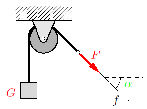
A single force is characterized by three properties: magnitude, direction, and point of application. The quantitative effect of a force is given by its magnitude. A qualitative feeling for the magnitude is conveyed by different muscle tensions when we lift different bodies or when we press against a wall with varying intensities. The magnitude F of a force can be measured by comparing it with gravity, i.e., with calibrated or standardized weights. If the body of weight G in Fig. 1 is in equilibrium, then F = G. The “Newton”, abbreviated N, is used as the unit of force.

From experience we also know that force has a direction. While gravity always has an effect downwards (towards the earth’s center), we can press against a tabletop in a perpendicular or in an inclined manner. The box on the smooth surface in Fig. 2 will move in different directions, depending on the direction of the force exerted upon it. The direction of the force can be described by its line of action and its sense of direction (orientation). In Fig. 1, the line of action f of the force F is inclined under the angle α to the horizontal. The sense of direction is indicated by the arrow.

What is a Force and How to Represent it?
Figure 2
What is a Force and How to Represent it?
Figure 3
Finally, a single force acts at a certain point of application. Depending on the location of point A in Fig. 2, the force will cause different movements of the box. A quantity determined by magnitude and direction is called a vector. In contrast to a free vector, which can be moved arbitrarily in space provided it maintains its direction, a force is tied to its line of action and has a point of application.
Therefore, we conclude:
The force is a bound vector.

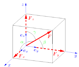
According to standard vector notation, a force is denoted by a boldfaced letter, for example by F, and its magnitude by |F| or simply by F. In figures, a force is represented by an arrow, as shown in Figs. 1 and 2. Since the vector character usually is uniquely determined through the arrow, it is usually sufficient to write only the magnitude F of the force next to the arrow. In Cartesian coordinates (see Fig. 3), the force vector can be represented using the unit vectors ex, ey, eby,

What is a Force and How to Represent it?

Applying Pythagorean theorem in space, the force vector’s magnitude F is given by

What is a Force and How to Represent it?

The direction angles and therefore the direction of the force follow from
What is a Force and How to Represent it?

The theoretical basis of the method of joints for truss analysis has already been discussed in this article '3 methods for truss analysis'. " 2 examples will be presented in this this article to clarify those concepts further.

Example 1

The truss shown in Fig. 1 is loaded by an external force F. Determine the forces at the supports and in the members of the truss.

Solved Examples for Method of Joints for Truss Analysis
Figure. 1
Solution:

Fig. 1a represents a simple truss that is completely constrained against motion. Therefore, it is statically determinate. The members of the truss are numbered in the free-body diagram of the complete truss (Fig. 1b). Zero-force members are identified by inspection and marked with zeroes: member 4 (according to Rule 2), the members 5 and 9 (Rule 3) and the members 10 and 13 (Rule 1). To further reduce the number of unknown forces, we compute the support forces by applying the equilibrium conditions to the whole truss.
Solved Examples for Method of Joints for Truss Analysis
Fig. 1c shows the free-body diagrams of the joints. As previously stated, we assume that every member is subjected to tension. Accordingly, all of the corresponding arrows point away from the joints. Zero-force members are omitted in the free-body diagrams. Therefore, joint VII need not be considered. Applying the equilibrium conditions to each joint yields
Solved Examples for Method of Joints for Truss Analysis
These are 11 equations for the 8 unknown forces in the members and the 3 forces at the supports. Since the support forces have been computed in advance and are already known, the analysis is simplified, and three equations may be used as a check on the correctness of the results. Using the geometrical relations
Solved Examples for Method of Joints for Truss Analysis
It is useful to present the results in dimensionless form in a table, including negative signs:
Solved Examples for Method of Joints for Truss Analysis
The negative values for the members 1, 2, 6, 7 and 11 indicate that these members are under compression.

Example 2

Fig. 2 shows a spatial truss loaded by two external forces F at the joints IV and V. Compute the forces in the members 1-6.
Solved Examples for Method of Joints for Truss Analysis
Figure. 2
Solution:

We free the joints V and IV by passing imaginary cuts through the bars, and we assume that the members 1-6 are in tension. The vector equations of equilibrium for these joints are given by
Solved Examples for Method of Joints for Truss Analysis

The initially unknown unit vectors can be determined from the vectors connecting adjacent joints, e.g., for e(V/VI) we obtain
Solved Examples for Method of Joints for Truss Analysis
Similarly, the other unit vectors are

Solved Examples for Method of Joints for Truss Analysis

Introducing these into the two vector equations we get the six scalar equations

Solved Examples for Method of Joints for Truss Analysis
Their solution yields the forces

Solved Examples for Method of Joints for Truss Analysis

A truss is a structure composed of slender members that are connected at their ends by joints. The truss is  one of the most important structures in engineering applications. After studying this chapter, students should be able to recognise if a given truss is statically and kinematically determinate. In addition, they will become familiar with methods to determine the internal forces in a statically determinate truss.

A structure that is composed of straight slender members is called a truss. To be able to determine the internal forces in the individual members, the following assumptions are made:

1. The members are connected through smooth pins (frictionless joints).
2. External forces are applied at the pins only.

A truss that satisfies these assumptions is called an “ideal truss”. Its members are subjected to tension or to compression only. In real trusses, these ideal conditions are not exactly satisfied. For example, the joints may not be frictionless, or the ends of the members may be welded to a gusset plate. Even then, the assumption of frictionless pin-jointed connections yields satisfactory results if the axes of the members are concurrent at the joints. Also, external forces may be applied along the axes of the members (e.g., the weights of the members). Such forces are either neglected (e.g., if the weights of the members are small in comparison with the loads) or their resultants are replaced by statically equivalent forces at the adjacent pins.
Statically Determinate Trusses
Fig. 1

In this article we focus on plane trusses; space trusses can be treated using the same methods. As an example, consider the truss shown in Fig. 1. It consists of 11 members which are connected with 7 pins (the pins at the supports are also counted). The members are marked with Arabic numerals and the pins with Roman numerals.

To determine the internal forces in the members we may draw a free-body diagram for every joint of the truss. Since the forces at the pins are concurrent forces, there are two equilibrium conditions at each joint. In the present example, we thus have 7·2 = 14 equations for the 14 unknown forces (11 forces in the members and 3 forces at the supports).

A truss is called statically determinate if all the unknown forces, i.e., the forces in the members and the forces at the supports, can be determined from the equilibrium conditions. Let a plane truss be composed of m members connected through j joints, and let the number of support reactions be r. In order to be able to determine the m + r unknown forces from the 2j equilibrium conditions, the number of unknowns has to be equal to the number of equations:

2 j = m + r (Equation 1)

This is a necessary condition for the determinacy of a plane truss. As we shall discuss later, however, it will not be sufficient in cases of improper support or arrangement of the members. If the truss is rigid, the number of support reactions must be r = 3. In the case of a space truss, there exist three conditions of equilibrium at each joint, resulting in a total of 3 j equations.
Therefore,
3 j = m + r (Equation 2)


is the corresponding necessary condition for a space truss. If the truss is a rigid body, the support must be statically determinate: r = 6.
Understanding trusses
Fig. 2

For the truss shown in Fig. 2a we have j = 7, m = 10 and r = 2 · 2 (two pin connections). Hence, since 2 · 7 = 10+4, the necessary condition (Equation 1) is satisfied. The truss is, in addition, completely constrained against motion. Therefore, it is statically determinate.

A truss that is completely constrained against motion is called a kinematically determinate truss. In contrast, a truss that is not a rigid structure and therefore able to move is called kinematically indeterminate. This is the case if there are fewer unknowns than independent equilibrium conditions. If there are more unknowns than equilibrium conditions, the system is called statically indeterminate. We shall only consider trusses that satisfy the necessary conditions stated in Equations (1) or (2), respectively. Even then, a truss will not be statically determinate if the members or the supports are improperly arranged. Consider, for example, the trusses shown in Figs. 2b and 2c. With j = 6, m = 9 and r = 3 the necessary condition (1) is satisfied. However, the members 7 and 8 of the truss in Fig. 2b may rotate about a finite angle ϕ, whereas the members 5 and 8 of the truss in Fig. 2c may rotate about an infinitesimally small angle dϕ. Each of the improperly constrained trusses is statically indeterminate.

These articles might also interest you:
 Analysis of 2D Truss Structure in SAP 2000
3 Methods for Truss Analysis

When a beam is subjected to applied forces, internal forces develop in the beam. Since the beam has supports and the system is in an equilibrium condition, the beam should resist these internal forces. This type of force is called shear force, or simply shear. The magnitude of the shear has a direct effect on the magnitude of the shear stress in the beam, and also on the design and analysis of the structural members.
Shear forces develop along the entire length of the beam, and their magnitude varies at each cross section of the beam. They actually act perpendicularly to the longitudinal axis of the beam. Our main objectives in finding the shear in beams are twofold. First, we have to know the maximum value of the shear in order to design the beam properly so that it can resist overall shear and will not fail when it is loaded.
The second objective is to calculate the values of shear along the length of the beam, so that we can find out where the beam fails under bending and where the shear value is zero.

As mentioned earlier, the designer must first know the magnitude of the shear force at any section of the beam to get the right picture of beam design. The magnitude of shear force at any section of the beam is equal to the sum of all the vertical forces either to the right or to the left of the section. To compute the shear force for any section of the beam, we simply call the upward forces (reactions) positive and downward forces (loads) negative. Then, the magnitude of the shear force at any section of the beam is equal to sum of the reactions minus the sum of the loads to the left of the section. This can be stated as:
Shear = Reactions - Loads
Example:
Find the shear force at sections C, D, and E for the simply supported beam shown (Fig. 1).
Computation of Shear Force
Figure 1
First, we calculate the reactions.

RA + RB = 15,000 lb 

Using the moment equilibrium equation,

RA(10) - 5000(8) -10,000(2) = 0
10(RA) = 60,000
RA = 6000 lb
and
RB = 9000 lb

Point C

We usually represent a shear force by V, and we designate this shear force at C as Vc.
Vc = +6000 - 0 = 6000lb

Point D

Vd =  +6000 - 5000 = +1000 lb

Point E


Ve = +6000 - 5000 - 10,000 = -9000 lb

Author Name

Engineeersdaily

Contact Form

Name

Email *

Message *

Powered by Blogger.